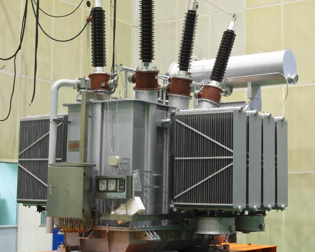
Power transformers convert power-level voltages from one level or phase configuration to another. They can include features for electrical isolation, power distribution, and control and instrumentation applications. Transformers typically rely on the principle of magnetic induction between coils to convert voltage and/or current levels.

Power transformers can be configured as either a single-phase primary configuration or a three-phase configuration. The size and cost of a transformer increases when you move down the listing of primary windings. Single-phase primary configurations include single, dual, quad (2+2), 5-lead, and ladder. A 5-Lead primary requires more copper than a Quad (2+2) primary. A Ladder is the least economical primary configuration. Three-phase transformers are connected in delta or wye configurations. A wye-delta transformer has its primary winding connected in a wye and its secondary winding connected in a delta. A delta-wye transformer has its primary winding connected in delta and its secondary winding connected in a wye. Three phase configuration choices include delta - delta, delta - wye (Y), wye (Y) – wye (Y), wye (Y) – delta, wye (Y) – single-phase, delta – single phase, and international. Primary frequencies of incoming voltage signal to primaries available for power transformers include 50 Hz, 60 Hz, and 400 Hz. 50 Hz is common for European power. 60 Hz is common in North American power. 400 Hz is most widely used in aerospace applications. The maximum primary voltage rating is another important parameter to consider. A transformer should be provided with more than one primary winding if it is to be used for several nominal voltages.
Other important specifications to consider when searching for power transformers include maximum secondary voltage rating, maximum secondary current rating, maximum power rating, and output type. A transformer may provide more than one secondary voltage value. The Rated Power of the transformer is the sum of the VA (Volt x Ampere) for all of the secondary windings. Output choices include AC or DC. For Alternating Current waveform output, voltage the values are typically given in RMS values. Consult manufacturer for waveform options. For direct current secondary voltage output, consult manufacturer for type of rectification.
Vector Group
Transformer name plates carry a vector group reference such as Yy0, Yd1, Dyn11, etc. This relatively simple nomenclature provides important information about the way in which three phase windings are connected and any phase displacement that occurs.
Winding Connection
High Voltage always capital letter:
- D: Delta Connection
- Y: Star Connection
- Z: Interconnected Star
- N: Neutral Brought Out
Low Voltage always small letter:
- d: Delta Connection
- y: Star Connection
- z: Interconnected Star
- n: Neutral Brought Out
Phase Displacement
Phase rotation is always anti-clockwise. Use the hour indicator as the indicating phase displacement angle. Because there are 12 hours on a clock, and a circle consists out of 360°, each hour represents 30°.
Thus 1 = 30°, 2 = 60°, 3 = 90°, 6 = 180° and 12 = 0° or 360°. The minute hand is set on 12 o'clock and replaces the line to neutral voltage (sometimes imaginary) of the HV winding. This position is always the reference point. Because rotation is anti-clockwise, 1 = 30° lagging (LV lags HV with 30°) and 11 = 330° lagging or 30° leading (LV leads HV with 30°).
Examples below are commonly vector group used in transformer:
- Dd0: Delta connected HV winding, delta connected LV winding, no phase shift between HV and LV.
- Dyn11: Delta connected HV winding, star connected LV winding with neutral brought out, LV is leading HV with 30°.
- YNd5: Star connected HV winding with neutral brought out, delta connected LV winding, LV lags HV with 150°.
- YNa0d11: Star connected HV winding with neutral brought out, auto transformer with 0° displacement. LV winding delta conected leading HV by 30°.
The phase-bushings on a three phase transformer are marked either ABC, UVW or 123 (HV-side capital, LV-side small letters).
Two winding, three phase transformers can be devided into four main categories (clock hour number and phase displacement of those most frequently encountered in practice in brackets).
- Group I: (0 o'clock, 0°) - delta/delta, star/star.
- Group II: (6 o'clock, 180°) - delta/delta, star/star.
- Group III: (1 o'clock, -30°) - star/delta, delta/star.
- Group IV: (11 o'clock, +30°) - star/delta, delta/star.
Using vector group (example):
- Group I:
Example: Dd0 (no phase displacement between HV and LV) - The conventional method is to connect the red phase on A/a, Yellow phase on B/b, and the Blue phase on C/c. Other phase displacements are possible with unconventional connections (for instance red on b, yellow on c and blue on a). By doing some unconventional connections externally on one side of the transformer, an internal connected Dd0 transformer can be changed either to a Dd4(-120°) or Dd8(+120°) connection. The same is true for internal connected Dd4 or Dd8 transformers. - Group II:
Example: Dd6 (180° displacement between HV and LV) - By doing some unconventional connections externally on one side of the trsf, an internal connected Dd6 transformer can be changed either to a Dd2(-60°) or Dd10(+60°) connection. - Group III:
Example: Dyn1 (-30° displacement between HV and LV) - By doing some unconventional connections externally on one side of the trsf, an internal connected Dyn1 transformer can be changed either to a Dyn5(-150°) or Dyn9(+90°) connection. - Group IV:
Example: Dyn11 (+30° displacement between HV and LV) - By doing some unconventional connections externally on one side of the trsf, an internal connected Dyn11 transformer can be changed either to a Dyn7(+150°) or Dyn3(-90°) connection.
Additional Note:
By doing some unconventional connections externally on both sides of the trsf, an internal connected Group III or Group IV transformer can be changed to any of these two groups. Thus, an internal connected Dyn1 transformer can be changed to either: Dyn3, Dyn5, Dyn7, Dyn9 or Dyn11 transformer, by doing external changes on both sides of the transformer. This is just true for star/delta or delta/star connections.
Changes for delta/delta or star/star transformers between Group I and Group II can just be done internally.
Cooling Method
As a point of clarification, the cooling classes of transformers have changed in recent years and are explained in the following infor-mation. The IEEE transformer cooling designations were changed to become consistent with the IEC (IEC 60076-2: 1998). The new classifications are detailed in IEEE C57.12.00-2000.
The new cooling designations have four-letter descriptions that indicate specific criteria relative to:
- The type of oil.
- How the oil is internally circulated.
- What is used to cool the oil.
- How the oil is externally cooled.
As an example:
First Letter - Internal cooling medium in contact with the windings.
- O: Mineral oil or synthetic insulating liquid with fire point < 300°C
- K: Insulating liquid with fire point > 300°C
- L: Insulating liquid with no measurable fire point
Second Letter - Circulation mechanism for internal cooling medium.
- N: Natural convection flow through cooling equipment and in windings
- F: Forced circulation through cooling equipment (i.e., coolant pumps) and natural convection flow in windings (also called non-directed flow)
- D: Forced circulation through cooling equipment, directed from the cooling equipment into at least the main windings
Third Letter - External cooling medium
- A: Air
- W: Water
Fourth Letter - Circulation mechanism for external cooling medium
- N: Natural convection
- F: Forced circulation (fans air cooling or pumps water cooling)
Comparison of past transformer cooling designations versus present-day transformer cooling designations is detailed in the following table:
| Present Designations | Previous Designations |
|---|---|
| ONAN | OA |
| ONAF | FA |
| ONAN/ONAF/ONAF | OA/FA/FA |
| ONAN/ONAF/OFAF | OA/FA/FOA |
| ONAN/ODAF | OA/FOA |
| ONAN/ODAF/ODAF | OA/FOA/FOA |
| OFAF | FOA |
| OFWF | FOW |
| ODAF | FOA |
| ODWF | FOW |
- ODAF: Oil Directed Air Forced
- ODWF: Oil Directed Water Forced
- OFAF: Oil Forced Air Forced
- OFWF: Oil Forced Water Forced
- ONAF: Oil Natural Air Forced
- ONAN: Oil Natural Air Natural
Tap Changer Type
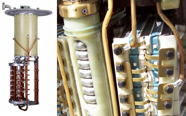
In low power, low voltage transformers, the tap point can take the form of a connection terminal, requiring a power lead to be disconnected by hand and connected to the new terminal. Alternatively, the process may be assisted by means of a rotary or slider switch.
- Off Load Design (NLTC): Because the different tap points are at different voltages, the two connections should not be made simultaneously, as this short-circuits a number of turns in the winding and would result in an excessive circulating current. This therefore demands that the power to the load be physically interrupted during the switchover time. Off-load tap changing is also employed in high voltage transformer designs, though it is only applicable to installations in which loss of supply can be tolerated.
- On Load Design (OLTC): Because interrupting the supply is usually unacceptable for a power transformer, these are often fitted with a more expensive and complex on-load tap-changing (OLTC) mechanism. On-load tap changers may be generally classified as mechanical; or as electronic, which in turn may be either assisted or solid state.

Energy Losses
An ideal transformer would have no energy losses, and would therefore be 100% efficient. Despite the transformer being amongst the most efficient of electrical machines, with experimental models using superconducting windings achieving efficiencies of 99.85%, energy is dissipated in the windings, core, and surrounding structures. Larger transformers are generally more efficient, and those rated for electricity distribution usually perform better than 95%. A small transformer, such as a plug-in "power brick" used for low-power consumer electronics, may be no more than 85% efficient; although individual power loss is small, the aggregate losses from the very large number of such devices is coming under increased scrutiny.

Losses in the transformer arise from:
- Winding Resistance:
Current flowing through the windings causes resistive heating of the conductors. At higher frequencies, skin effect and proximity effect create additional winding resistance and losses. - Hysteresis Losses:
Each time the magnetic field is reversed, a small amount of energy is lost due to hysteresis within the core. For a given core material, the loss is proportional to the frequency, and is a function of the peak flux density to which it is subjected. - Eddy Currents:
Ferromagnetic materials are also good conductors, and a solid core made from such a material also constitutes a single short-circuited turn throughout its entire length. Eddy currents therefore circulate within the core in a plane normal to the flux, and are responsible for resistive heating of the core material. The eddy current loss is a complex function of the square of supply frequency and inverse square of the material thickness. - Magnetostriction:
Magnetic flux in a ferromagnetic material, such as the core, causes it to physically expand and contract slightly with each cycle of the magnetic field, an effect known as magnetostriction. This produces the buzzing sound commonly associated with transformers, and in turn causes losses due to frictional heating in susceptible cores. - Mechanical Losses:
In addition to magnetostriction, the alternating magnetic field causes fluctuating electromagnetic forces between the primary and secondary windings. These incite vibrations within nearby metalwork, adding to the buzzing noise, and consuming a small amount of power. - Stray Losses:
Leakage inductance is by itself lossless, since energy supplied to its magnetic fields is returned to the supply with the next half-cycle. However, any leakage flux that intercepts nearby conductive materials such as the transformer's support structure will give rise to eddy currents and be converted to heat.
 Reviewed by Unknown
on
10:20 AM
Rating:


